do it yourself energy products, save energy with skylights, new construction, home builders, home builders, home builder, architects, daylighting, radient barrier, LED lighting
 Contact us: 602-867-3176
PROPRIETARY PATENTED SUSTAINABLE BUILDING PRODUCTS
![]()
TESTING OF RBS CHIPS
RBS Chips were to be tested side by side at FSEC against two other types of radiant barriers and a comparison cell with R-19 insulation and no radiant barrier. The main purpose of this test was to measure degradation due to dust accumulation over time, a significant problem with previous radiant barrier products placed above the insulation. The many layers of our RBS Chip overcome the dust problem and continue to offer performance and energy savings.
The testing showed our RBS Chips returned a 42% percent reduction after the introduction of dust. As can be seen below, the tests were performed in 1989. The chips tested during this evaluation were a hand made, prototype product which has since been replaced by a higher performing design which offers better coverage, increased protection from dust. It is not uncommon to see a 25% to 40% decrease in total monthly energy costs and increased comfort after the application of RBS Chips. These savings are both for cooling costs and heating costs in colder climates.
Further, not only is the multiple layers of RBS used to overcome the dust issue (that's the main claim in the patent), more than one layer of a reflective surface facing other reflective surfaces further benefits the performance.
DETAILS OF TEST
Three types of floor mounted radiant barriers were tested. The purpose of this test was to gauge the degradation of performance after the accumulation of dust.
Powdered gypsum drywall (emissivity .95), was blown into each test cell completely covering the radiant barriers. Only RBS Chips continued working. Once completely covered, the single layer radiant barrier ceased performing. Not difficult to comprehend given the fact that infrared energy is an electromagnetive wave form and bounces off reflective surfaces. More dust was then blown in and a small percentage of performance loss occurred.
Unfortunately, as can be seen below, the test has been marked "CONFIDENTIAL" (since 1989) and cannot be reprinted (see cover page of test below).
We were contacted on 6/29/98 by the Florida utility who ordered the test and was told in writing by their senior attorney to "cease and desist in all respects from representing to the public in any manner, or by any means any information on the said report. In addition (name withheld), demands that you immediately remove the portion of the Web Page dealing with the "1989 Florida (name withheld) Test. If the Web Page article is not deleted within 48 hours of receipt of this letter, then (name withheld) will seek whatever legal remedies are available without any further notice to you." Below is the cover sheet name witheld.
Other Testing by Electric Utilities
In the summer of 1993 Arizona Public Service Company (APS) began testing the performance of three Radiant Barrier Systems (RBS) against a control house with no RBS. Although APS never made these findings public, subsequent tests on the same homes in the summer of 1996 parallels the findings in 1993.These tests were performed using four identical, unoccupied homes for data collection and measurement of power usage. All power was shut off in these homes except for the heat pump. This was a very well planned and scientific test. The Arizona Department of Commerce Energy office did pressure testing and duct sealing to insure all homes were as close as possible to obtain accurate data.
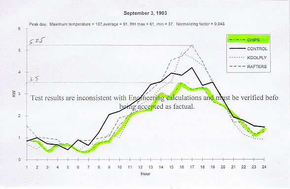
The tests ran for a year as APS collected data. The graph below illustrates a typical day of electricity consumed by all of the RBS products as tested against the control home without RBS (the dark black line). Notice the RBS Chip outperformed all other types of radiant barrier tested.
The graph above illustrates some interesting points:
1) Sheets of radiant barrier stapled inside the attic under the roof has been the recommended placement by the U.S. Department of Energy since 1991. The graph clearly shows this application of radiant barrier to energy consumption and demand. Late in the day (4pm-5pm), the reflective properties of radiant barrier under the roof decking, faces the now superheated insulation and prevents heat from escaping. Heat becomes trapped in the attic much like a thermos bottle increasing demand and electrical consumption. Further, increasing the temperature of a roofing material surely cannot increase the life of a roof or tile underlayment.2) Plywood laminated with radiant barrier has a similar effect though not as drastic as the rafter application.
The explanation for this is simple once emissivity and convection are understood. The plywood roof deck, with a lowered emissivity due to the placement of radiant barrier, raises the temperature of the wood (much like a chrome car bumper on a sunny day). This in turn increases the convective currents in the attic which in turn superheats the insulation to a temperature higher than at home without radiant barrier! Manufacturers of this product claim lower attic temperatures at noon which can be seen in the graph above. It is not until 4-5pm that the trapped heat becomes apparent and raises the need for electricity higher than that of a home without a radiant barrier. Notice only the RBS Chip was below the control home all day. Keep in mind this is one day. Truth is, RBS Chips keep you home more comfortable and energy efficient everyday.
4) One aspect not addressed in this test of energy use is the effect a radiant barrier has on comfort. While air temperature, humidity and air movement affect human comfort, the number one contributing factor is Mean Radiant Temperature (MRT). The emissivity, surface temperature and proximity affect human comfort the most. Virtually eliminating a radiant heat load from the ceiling right above you will have an immediate and profound impact on comfort. A thermostat on the wall measuring sensible heat only cannot sense this. We have found in the two decades of installing multiple layered low e surfaced film above attic insulation that customers immediately relate that they must raise the temperature of the thermostat to obtain the same comfort.
5) As can be seen in the graph, a radiant barrier placed directly over the insulation significantly reduces energy costs by keeping the insulation cooler. Our patented Radiant Barrier Chip product overcomes the anomalies once associated with this placement: performance degradation due to dust accumulation, labor intensive installations and moisture condensation in colder climates. Parrallel thinking went into the design of our latest reflective insulation, "Thermal Control Membrane" for hot and tropical applications.
University of Arizona School of Architecture Testing
In 1989 we worked with a home builder who was interested in using our products on their homes. He built two identical homes side by side, one built to code with R19 in the walls and R30 in the attic.
Home #2 had zero insulation the walls or attic, only TCM.
Home #1 had no one occupying is during the day as both occupants worked and turned the thermostat to 80F
Home #2 (no insulation) was occupied by a family of nine and had the thermostat set at 78F
The ASU School of Architecture, headed by Dr. Byard Wood, came to the site and installed 15 thermocouples (7 thermocouples in each home and one ambient sensor.
The house with no insulation was using 35% less power than the insulated house. This discovery led to us writing a white paper called the "sweater effect".
Building a new home? Adding a room? Want to decrease your electric bill? Increase your comfort? Simply submit your drawings to us and we will assist you in building the most comfortable, energy efficient home possible....economically. Or drop us email anytime if you have questions.
Questions? Call us: 602-867-3176
Email us Click here!
Back to Top
Back to Frequently Asked Questions Page
Back to Main Page

Web page design and maintained by B Rad Design Group
Copyright 1997-2020 Horizon Energy Systems. All rights reserved.
Information in this document is subject to change without notice.
Other products and companies referred to herein are trademarks or registered trademarks
of their respective companies or mark holders.

